Data input
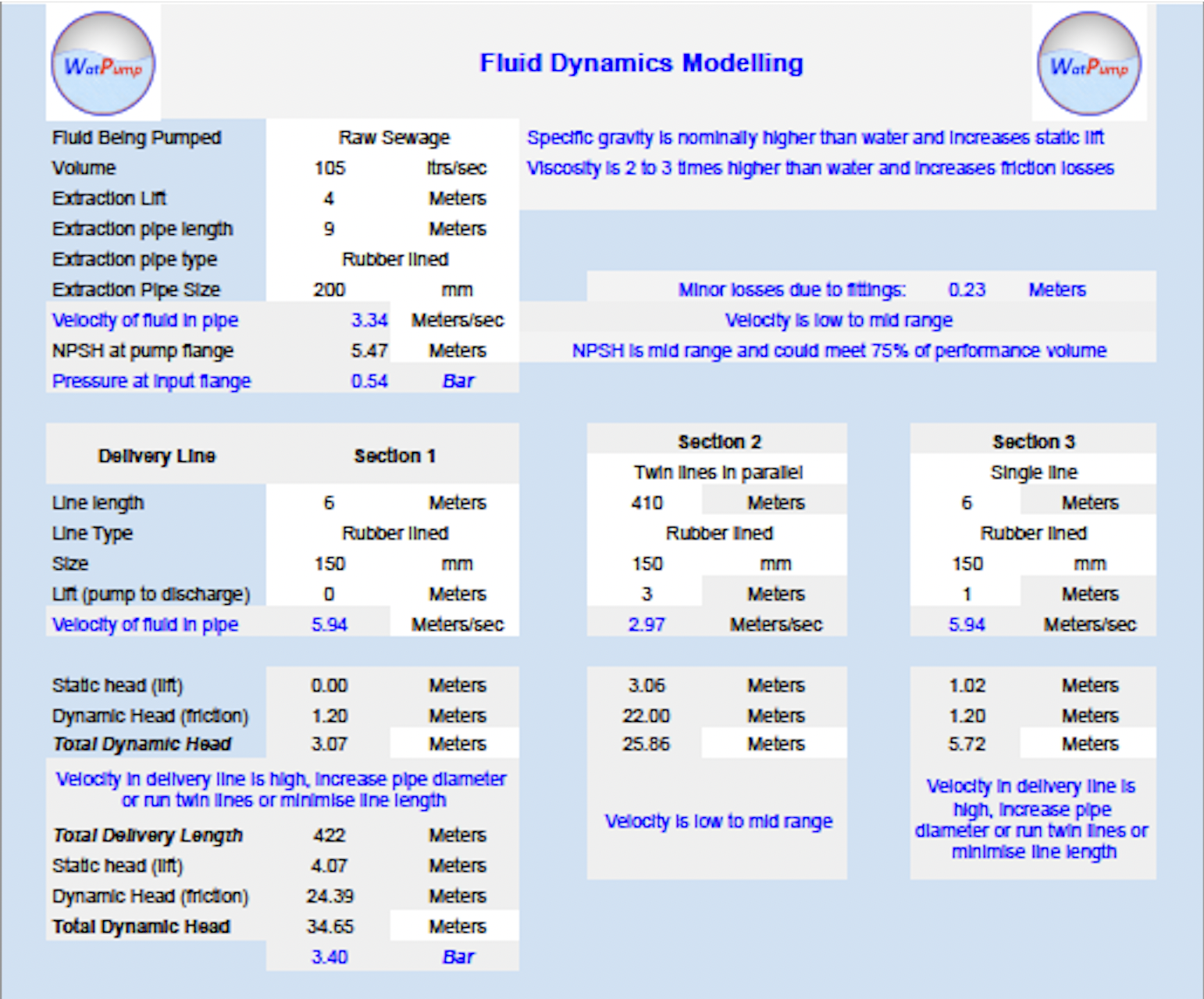
Hard hose is common in many temporary pumping applications, HDPE is more efficient and often specified for medium term projects".
Hints are provided within the workbook for guidance and alternate solutions
How to run pressure loss calculations
The pressure loss application requires some basic inputs with guidance at each step based on theory and practical experience
Fluid type, this is selected from a drop down box with a range of typical fluids from water, waste water products, drilling fluids and salt water. Viscosity and specific gravity (or mass) is provided for each of these fluids.
Unit selection - the application can work in SI (metric), Us or Imperial units. This should be selected first, there are subgroups within this range as well (eg: ltrs/sec, m3/hr)
Volume to be pumped - this can be entered as ltrs/sec, m3/hr, gallons/min
Extraction lift - this is a critical element to pump performance, the application will "flag" if the extraction lift is outside of practical extraction parameters
Extraction length will affect friction losses which are critical to extraction performance, these losses can be mitigated with the diameter of extraction hose or pipe used
Delivery line - this can be calculated using a single sector or in more complex deliveries multiple line sectors can be utilised. Line type, line length and line diameter can be entered for each selected line segment used. The lift from the pump to the discharge point or highest point in the delivery line is also required for complete calculation.
Minor Losses
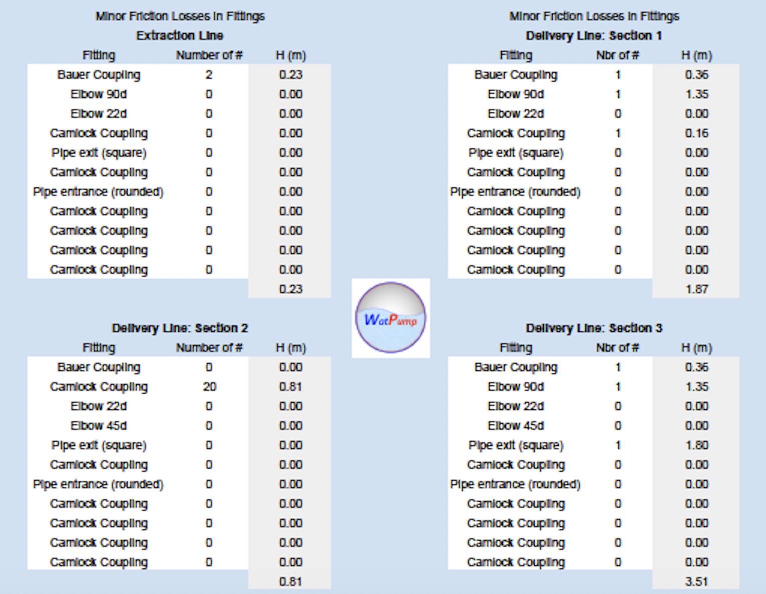
Minor losses are the pressure losses due to line connections, bends and other line characteristics (including square-end discharge and extraction points).
Minor losses are frequently ignored in Fluid Dynamics but these can be critical in the extraction modelling (extraction modelling is critical and sensitive to losses). With the delivery pressure and volume minor losses can also reduce the volume output.
K-values are provided for fittings, these allow the pressure loss through fittings in a a pipe to be calculated. It should be noted that K values are provided by manufacturers and are typically for steel fittings, it will provide good guidance and indicate if the minor losses are critical to the line design.
Data input
Pump Selection
Pump Selection
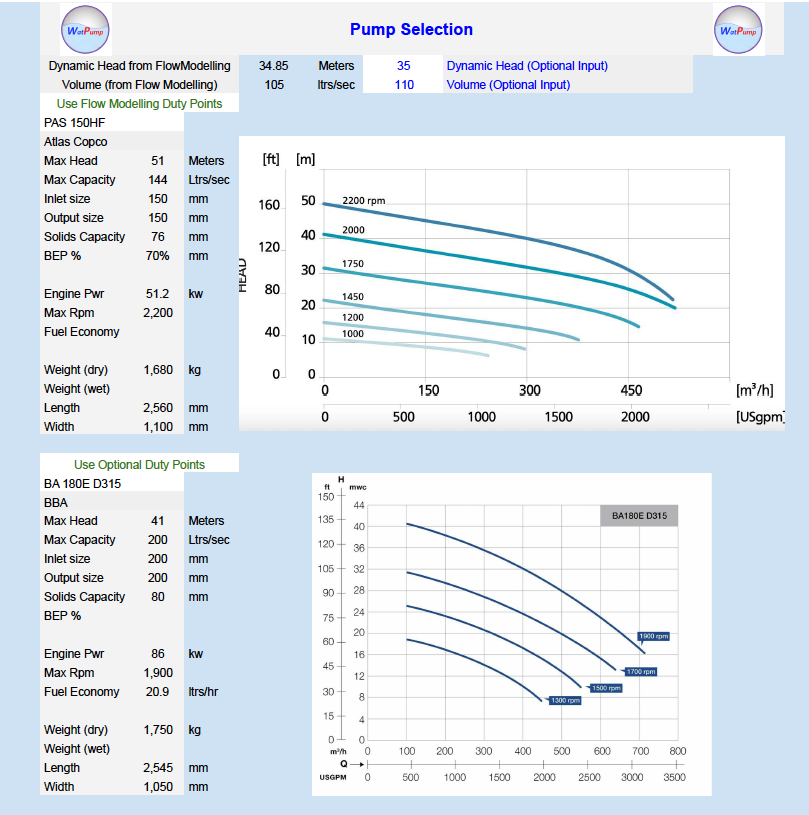
The pump selection options are derived from the 'duty point' (volume and pressure). Pump selection options enable the option of using the duty point from the Fluid Dynamic Calculations; alternately a manually entered duty point can be inputted into the pump selection form. .
The user can select a pump from the drop down list. The selected pumps will provide the performance curve and core data to enable comparison between pumps.
Optimum performance is generally in the centre of the curve below the top performance line. Pumps can run at lower rpm to achieve performance points at the lower part of their performance curves
Extraction NPSH is critical to the pumps performance, this curve is frequently not provided in the main pump curve, guidance is provided in the Fluid Dynamic worksheet but in critical applications with low NPSH further consideration should be given.
Solids handing capacity is critical in waste water applications. Typically waste water suitable pumps will have solids handling of 70mm (3") or better
NPSH
NPSH stands for Net Positive Suction Head and is a measure of the pressure experienced by a fluid on the suction side of a centrifugal pump.
A low NPSH has two main effects on the pumping application.
The maximum theoretical NPSH is 10.2m (1 Bar, atmospheric pressure). In practical terms an NPSH of 8 is high and 2 is likely the lowest operating NPSH point.
In applications where low NPSH is unavoidable the pump selected will likely need to be a higher capacity (by volume) pump operating at its lower performance point (eg: a longer pump running at lower rpm's or towards the left hand side of the performance curve).
Friction losses can be mitigated with extraction pipe design (eg: larger pipe diameter or type). Extraction lift cannot be mitigated and can be the determing factor in surface pumping suitability.
NPSH
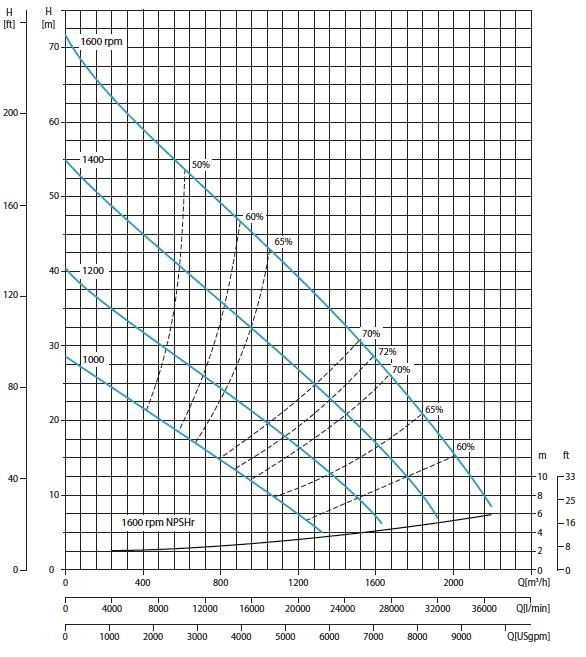
The NPSHr curve is the lower (black) curve. NPSHr is NPSH required for this pump performance curve.
Energy consumption
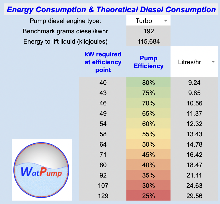
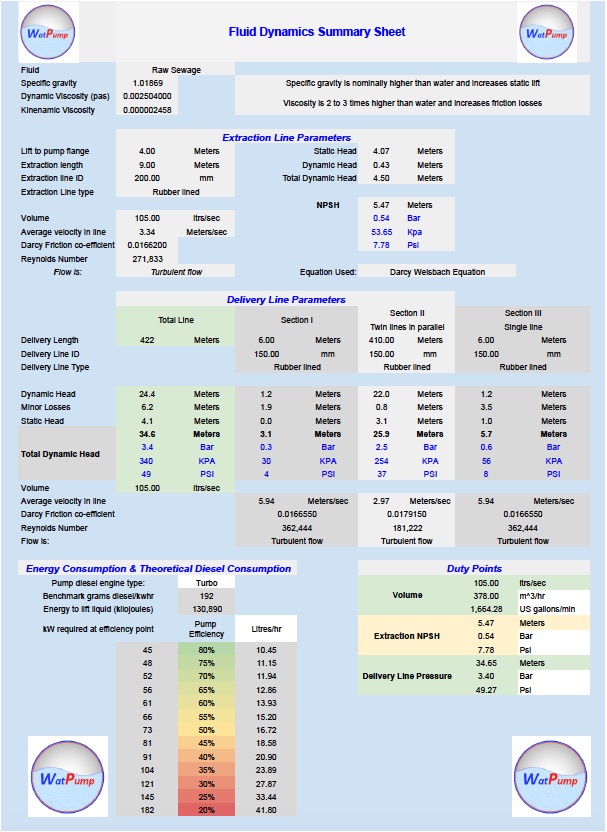
Energy consumption table calculated from the volume and pressure calculated within the Fluid Dynamics worksheet
Energy consumption
Pump manaufacturers will frequently claim 'best fuel efficiency' and give fuel consumption at either a single performance point or alternately a high and low figure. In real world experience the fuel consumption varies widely depending on how hard a pump is working
The energy required to pump water can be calculated using mass (volume) and pressure (height). Using a potential energy equation, the energy consumed (kilojoules) can be converted to kw/hrs, diesel engines have diesel consumption per kw/hr ratings for either turbo or non-turbo engines.
Fuel consumption varies considerably across the efficiency range. With a pump working within the central zone of its performance curve an efficiency of 75% to 55% should be achievable. If it is operating on the perimeter of its performance curve or the pump is in poor condition it will likely operate between 20% and 40% efficiency
Summary Sheet and Certificate
A summary page and certificate is produced with:
Summary Sheet and Certificate
